Thursday, December 28, 2017

The Importance of Water

Life as we know it is unsustainable without water. Water is so essential for life that civilizations have risen and collapsed, due to their capacity, or lack thereof, to harvest a continual supply of water.

Without question, water along with oxygen is our most precious resource, and great care must be taken to protect it. Governments around the world have recognized this fact and have crafted byzantine codifications mandating protection protocols, treatment programs, and storage and distribution regulatory requirements.

The most predominant problems facing the world in regards to water are:
 Quantity — Only 2.5% of the earth’s water is freshwater, and much of it is inaccessible as it is frozen in icecaps or glaciers, or in the ground.
 Quality — According to the United Nations, by the year 2025, 50% of the world’s population will be facing a daily struggle to find enough water to meet their basic needs.

Water is essential for human life.
While quantity effects many nations, quality is primarily a problem of the developing world. Modern water treatment systems throughout the developed world have eradicated most deadly pathogens, and thankfully your nightly news is not filled with stories of outbreaks of cholera or typhoid.
Because water is such a finite resource, and so basic to our survival, we must take every possible precaution in safeguarding it throughout its entire lifecycle: extraction, treatment, storage, distribution, and process.

Concrete is the preferred building material used in regards to water structures. Whether it’s a megalithic concrete dam, holding back tens of millions of gallons of water, or pretreatment and treatment units at your municipal water treatment plant, you will see that it’s made of concrete. Concrete is a great building material for water structures, as it is can be made fluid-proof and strong; has a very long lifecycle; and is relatively easy to manufacture and install almost anywhere in the world. On the downside, concrete can not be truly functional without the addition of joints, and joints will leak unless adequate provisions are made to fluid-proof them. This is the sole function of waterstop: to prevent the passage of fluids through concrete joints.

Saturday, December 09, 2017

Hydrophobic Waterstop for Concrete Joints

When most engineers or contractors think of a “waterstop” what they’re generally referring to is a 50-foot long section of a flexible, water-proof material (usually plastic or rubber), six to nine inches wide, and installed along the concrete joint in between the formwork. This waterstop is more accurately defined as a hydrophobic waterstop: A waterstop designed to prevent the passage of fluids by repelling them along and away from the waterstop product, and creating an internal dam at and along the concrete joint. Hydrophobicity is the amount of water repulsion of the surface of the waterstop, and can actually be measured: Place a drop of water on the flat side of the waterstop to be tested and measure the relief angle of the water drop. The sharper the angle the more hydrophobic the waterstop material is. An angle 90 degrees or greater makes the waterstop truly hydrophobic and this product will actively move fluids along the joint and away from the source.
A waterstop that will perform well must have adequate strength and extensibility to avoid be torn or ruptured by joint movement. The best waterstop products are able to maintain these properties (high tensile strength, good elongation [ASTM D-412]) when exposed to the installed environment for the service life of the structure. Exposure conditions which could affect a waterstop’s service life are:


  1. Temperature
  2. UV exposure
  3. Ozone exposure
  4. Chemical attack


Hydrophobic TPV Waterstop by Earth Shield
Because hydrophobic waterstops act as dams at the concrete joint, a general rule of thumb is the greater the size of a waterstop (waterstop size is actually it’s width, e.g. 4”, 6”, 9”, etc.), the greater the head pressure the waterstop will resist. A small 4” waterstop is more than suitable for a containment wall surrounding a tank farm, or even a swimming pool in a back yard, but would be completely inappropriate for the foot of a large dam. Giant concrete structures such as dams or locks will require 9” wide waterstops or greater.

It’s not just width (size) that effects waterstop performance, thickness also plays an important role. Just like conventional dams, the thicker waterstops are able to resist higher head pressures of water (or other aqueous fluids).

Because proper installation plays such a critical part in the effectiveness of a given waterstop system, the very best waterstops are those that can be fused and fabricated easily. For this reason, the majority of today’s design engineers specify and require thermoplastic waterstops (such as PVC or #waterstop), and not the earlier thermoset varieties (neoprene, SBR, natural rubber). Thermoplastic materials have the ability to be easily field fabricated for simple change of directions and the joining of straight lengths; whereas, the earlier thermoset rubber materials generally were ineffectively glued and clamped together causing a severe weakness in the waterstop diaphragm and leaking.

A waterstop’s cross-sectional area is called its profile, and there are lots of profiles to choose from, but really they all share the same basic anatomy: a series of fins or bulbs to provide interlock with the concrete, the body or web to provide the necessary rigidity and product width, and possibly a hollow cavity or bulb to enable the waterstop with additional movement properties.

By far, the largest difference between various waterstops on the market today are the polymers they are constructed of, and the services offered by various manufacturer’s. It is up to the individual designer to find a manufacturer that offers the desired set of services and support for their project. These after-sale services and support are truly what separates a great manufactured waterstop from a poor one. Just remember, “Choose wisely.” A waterstop is permanently installed in concrete (much like rebar) and there really are no second chances to get it right.

Thursday, November 16, 2017

We've Got Waterstop Splicing Irons

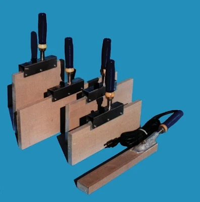
JPS Standard Irons are specifically designed for welding waterstops and other thermoplastic extruded profiles (expansion joints, seals, etc.). The temperature control can be adjusted from 250°F to 500°F to accommodate various ambient conditions and different polymers. All JPS Standard Irons are constructed with the highest quality components.

waterstop splicing irons
JPS Standard Waterstop Splicing Irons


Designed for the waterstop pro! Our Pro Series irons feature all the same attributes as our regular irons plus built-in thermometer, temperature control knob, outdoor-use power cord (UL and CSA approved), ergonomic vinyl grip, sealed elements, and a Silverstone coating that doesn't require covers.


  • Built-in analog thermometer
  • Sealed end caps (meets EU Standards)
  • Silverstone-coated — No Teflon® covers required
  • Better, ergonomic handgrip
  • 8-foot, CSA & UL certified, outdoor use power cord
  • Meets CEGS 03250 requirements
JPS Pro-Built Waterstop Splicing Iron

Saturday, October 21, 2017

Proper Installation of Expansion Board Cap Waterstop Profiles


  1. Part No. JP158 — 1” screed key cap, as manufactured by JP Specialties, Inc. (designed for keyed joints) 
  2. Part No. JP1225 — 1” integrated screed key cap seal waterstop, as manufactured by JP Specialties, Inc. (designed for keyed joints; if specified with factory installed brass eyelets use part no. EYJP1225) 
  3. Part No. JPEB350 — 1/2” integrated cap seal waterstop, as manufactured by JP Specialties, Inc. (designed for expansion joints; if specified with factory installed brass eyelets use part no. EYJPEB350) 
  4. Part No. JPEB375 — 3/4” integrated cap seal waterstop, as manufactured by JP Specialties, Inc. (designed for expansion joints; if specified with factory installed brass eyelets use part no. EYJPEB375) 
  5. Part No. JPEB375R — 3/4” integrated cap seal retrofit waterstop, as manufactured by JP Specialties, Inc. (designed for expansion joints; if specified with factory installed brass eyelets use part no. EYJPEB375R) 

Integrated expansion board cap waterstop systems are designed to replace post-applied joint sealant, and provide a fluid-tight internal seal like a traditional waterstop with a one-step, integrated unit. Earth Shield expansion board cap waterstop is installed on top of conventional expansion board filler or Earth Shield’s own chemical resistant, plastic expansion board. The expansion board acts as the form; therefore, no form splitting is necessary. This greatly accelerates the project schedule and provides a long lasting, attractive finished concrete joint. Earth Shield screed key cap slides over the top of metal screed key, eliminating the need for sealant. Like all our thermoplastic vulcanizate waterstops, Earth Shield integrated cap system waterstop can be heat-welded using a standard waterstop splicing iron. This allows for easy field fabrications, and allows the waterstop to function as a continuous, homogeneous, fluid-tight diaphragm. Waterstop change of directions can be purchased along with straight roll stock, and custom, fit-to-print waterstop modules are produced to order. Prefabricated ells, tees, tank pads, column fittings, and many others are in stock and ready to ship.
Preparation
  1. Protect waterstop from damage during progress of work.
  2. Clean concrete joint after first pour to remove debris and dirt.
Examination/Inspection
  1. Prior to placement of concrete notify engineer for field inspection approval.
  2. Inspect waterstop and field splices for defects.
  3. Upon inspection of waterstop installation, replace any damaged or unacceptable waterstop and dispose of defective material.
Installation
  1. Place the JP EBCapstop over the top of the expansion board.
  2. Securely fasten the JP EBCapstop the expansion board so that the JP EBCapstop is flat against the header board. Any kinks in the JP EBCapstop should be straightened out before it is fastened to the header board. The JP EBCapstop should be mechanically fastened (nails or staples) below the flange.
  3. The fastening devices should be placed every 6" to 12" on center to maintain the alignment of the JP EBCapstop along the header board. For the best protection against liquid penetration, care should be taken to not tear or puncture the JP EBCapstop above the flange.
  4. Pour the concrete and screed to the top of the JP EBCapstop. It is imperative that the concrete totally encapsulates the flange in order to eliminate any voids or honeycombing below the flange and to form a liquid tight barrier. Care should be taken if the concrete is vibrated or rodded to avoid damaging the JP EBCapstop.
  5. The concrete should be vibrated, or thoroughly rodded, near the joints to insure proper consolidation around and under the flanges.
Notes
  1. It is imperative that the concrete not be subjected to loads until it has reached the rated strength per the design requirements (minimum 3,000-psi).
  2. When pouring concrete in a checkerboard pattern the exposed edge of the expansion board must be protected from traffic and abuse. Driving over exposed header boards will initiate cracking. i.e. It is not good practice to drive over the header board onto or off of the poured slab. Doing so may cause cracking, even if the concrete has reached its design strength (3,000-psi minimum).
  3. Loads that exceed the rated strength of the concrete shall not be allowed. If cranes are to be used for tilt-up construction, the weight of the crane must be considered in the concrete strength specification.
For welding, fabrication, placement, execution, and quality assurance please follow all procedures stated in Earth Shield Master Specification Section 03250.

Thursday, October 05, 2017

Base Seal Waterstop

Base seal waterstop is ideal for flat pavement jobs such as runways, large containment slabs, etc. Base seal waterstop is by far the easiest waterstop to install... Simply lay the waterstop directly on the compacted sub-grade, place and finish concrete, and create control joint using saw cut or other method. The base seal provides a permanent, life-of-structure seal at the bottom of the joint. Base seal is suitable for construction, contraction (control), and expansion joints. Base seal should not be used on jobs that make interior wall transitions as the part is non-symmetrical and therefore cannot function correctly. For large hydrostatic head pressures (>50 foot) ribbed centerbulb should be used instead.


Monday, August 07, 2017

Stainless Steel Waterstop for High Heat Applications

Earth Shield® Stainless Steel Waterstop can stop even the most corrosive fluids in their tracks, even at severely elevated temperatures. A variety of metals, grades, and gauges are available. Earth Shield® utilizes 20 gauge 316 low carbon as our standard alloy, which offers broad spectrum corrosion resistance to most aggressive media, and is virtually untouched by the deleterious effects of ozone, making it an ideal choice for ozone contactor structures used in modern water treatment plants.

Hydrophobic SS Waterstop
1. Prevents the passage of extremely corrosive fluids (even at elevated temperatures) through concrete joints by creating an internal dam, spanning both sides of and running continuously along the concrete joint.
2. The most difficult to install waterstop, as split-forming is always necessary (with the exception of retrofit profiles). Also, TIG or MIG welding is required.
3. Contains no plasticizer to leach out (unlike PVC) from exposure to hydrocarbons, acids, ozone, ultraviolet radiation, or time.
4. Products are available for above- or below-grade; limited-moving or non-moving applications.
5. Designed to last the life of the concrete structure.
6. Able to withstand extreme temperature conditions (high heat, LNG, etc).

Earth Shield® Stainless Steel Waterstop is available in many standard shapes and sizes, including profiles for new construction and retrofit. All change of direction fabrications can be pre-manufactured leaving only straight butt welding for the field.

Friday, June 02, 2017

Waterstop Physical Properties

waterstop, waterstops, chemstop, fuelstop
There are a number of physical properties you should consider when choosing the right material for your waterstop application. These include hardness, tensile strength, modulus, elongation, tear resistance, and compression set.
Hardness — ASTM D2240
Hardness is resistance to indentation under specific conditions. There are currently two hardness tests that predominate in the rubber and plastic industry: Shore durometer and International Rubber Hardness Degrees (IRHD). Most commercially available waterstops use the Shore A scale; therefore, to evaluate waterstops look at the listed value and understand that the higher number means the harder (and stiffer to flexure) waterstop product.
100% 
Tensile Strength — ASTM D412
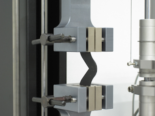
Typically noted in either pounds per square inch (psi) or megapascals (MPa), tensile strength is the amount of force required to break a plastic or rubber waterstop specimen. (To convert from MPa to psi, simply multiply the MPa figure by 145. For example, 14 MPa converts to 2,030 psi. Converting from psi to MPa is just a matter of dividing the psi number by 145.
Modulus — ASTM D412
Modulus is the force (stress) in pounds per square inch (psi) required to produce a certain elongation (strain). 100% is the most widely used figure for testing and comparison purposes of commercially available waterstops. Generally speaking, the harder a waterstop (ASTM D2240), the higher its modulus. Because it is basically a measure of tensile strength at a particular elongation (rather than at rupture), modulus is also known as tensile modulus or tensile stress.


Ultimate Elongation — ASTM D412
Elongation is the percentage increase in original length (strain) of a rubber or plastic waterstop specimen as a result of tensile force (stress) being applied to the specimen. Elongation is inversely proportional to hardness, tensile strength, and modulus. Therefore, the greater a waterstop’s hardness, tensile strength, and modulus, the less it will elongate under stress. It takes more force to stretch a hard waterstop having high tensile strength and high modulus than to stretch a soft material with low tensile strength and low modulus. Ultimate elongation is the elongation at the moment the specimen breaks. Per ASTM D412, ultimate elongation is expressed as a percentile; therefore, when comparing waterstops the higher the number (%) the better.

Tear Resistance (aka Tear Strength) — ASTM D412
Tear resistance (also known as tear strength) is resistance to the growth of a cut or nick in a waterstop specimen when tension is applied. Values are usually expressed in pound force per inch (lbf/in), so again, the waterstop with the higher value is superior, as it is more resistant to tearing.

Compression Set — ASTM D395
Compression set is the permanent deformation remaining when a force applied to a waterstop specimen for a period of time is removed. Tested under ASTM D395, compression set is expressed as a percentile that relates to the percentage of deformation compared to the waterstop’s original thickness. Therefore, a low value is better as it denotes the waterstop did not “take a set” and returned close to its original shape and size after the force is removed. A high value means the waterstop became deformed (squished) under pressure and did not return to its original shape and size. Compression set represents the percent of deflection that did not return.
There are a number of physical properties you should consider when choosing the right material for your waterstop application. These include hardness, tensile strength, modulus, elongation, tear resistance, and compression set.
Drinking Water Safe — NSF 61
Water is arguably the most valuable resource in the world. Today’s water treatment, distribution, and storage projects are under ever-increasing layers of regulations and requirements, one of the foremost being that components and materials that contact potable water not have potential adverse human effects.


NSF Standard 61 was developed to establish minimum requirements for the chemical contaminants and impurities that are indirectly imparted to drinking water from products, components, and materials used in drinking water systems.
Standard 61 is intended to cover specific materials or products that come into contact with drinking water, drinking water treatment chemicals, or both. The focus of Standard 61 is evaluation of contaminants or impurities imparted indirectly to drinking water.
In the U.S., 47 of 50 states have legislation that requires compliance with NSF Standard 61. Products that are NSF Certified against NSF/ANSI Standard 61 demonstrate compliance with both Canadian and U.S. Plumbing Codes. NSF Certification and Testing is widely accepted. NSF data is recognized by ASSE, BOCA, IAPMO, ICBO-ES, SBCCI, City of Los Angeles and many others.
Very few waterstops have NSF 61 certification, which is pretty surprising considering that waterstops are often installed in drinking water facilities. I believe this is one of the more important requirements for a waterstop (NSF 61 certification) and that specifiers should require it.

Resistance to Chemicals — ASTM D471
ASTM D471 tests the waterstop in a given concentration of a specific fluid* for 166 at hours at a specified temperature* (*customer request of fluid and usually 23°C for the temperature). After the testing time has elapsed, the waterstop is removed from the fluids and a variety of physical tests are performed that gauge its durability and corrosion resistance to the material it was immersed in. A waterstop that performs well in this test can be considered “chemical resistant,” but only to the specific fluid tested. In other words, a waterstop could be a good choice for fuel oil, but a poor choice for hydrochloric acid. This distinction is important, as no one metal or polymer waterstop is chemically resistant to everything.


Resistance to Ozone — ASTM D1171
ASTM D1171 tests the waterstop in a given concentration* of ozone (*usually expressed in Parts Per Million (PPM) or Parts Per  Hundred Million (PPHM). After the testing time has elapsed, the waterstop is removed from the ozone chamber and a variety of physical tests are performed that gauge its durability and corrosion resistance to the ozone it was exposed to. Because many waterstops fail in high concentrations of ozone, this is an important test when selecting a waterstop for an ozone contactor application. A waterstop that performs well in this test can be considered “ozone resistant,” but only to the concentration tested to.


Tuesday, May 09, 2017

How to Weld Plastic Waterstop

An initial warm up time of approximately 15 minutes is required to heat up splicing iron to the required temperature. Preheat Iron up to the following:
• For TPV / TPER Waterstop: 410 to 430°F
• For PVC Waterstop: 350 to 380°F
It is recommended to verify temperature using an external thermometer.
NOTE: The Peel and Stick Teflon® Cover is to remain on the iron during the welding process. DO NOT REMOVE.
CAUTION: Too high of a temperature will result in damage to waterstop welds, splicing iron cover, and possibly splicing iron.
1. Always cut square ends before welding waterstops. Never weld to extruded ends. Use flat work table to create field splices. Work area should be solid and have access to power supply and have jigs and fixtures to aid splicing.
2. Cut ends square, using a razor knife or circular saw equipped with a carbide tipped blade (10” diameters with 40 teeth) to ensure matching edges.
3. Preheat the iron to the desired temperature ranges. Place iron between butt ends. Keep waterstops in place until approximately 3/16” bead forms on each side of waterstops. Quickly remove splicing iron and gently press waterstops ends together until they bond (approximately 3 to 5 minutes or cool to touch). Cold water may be sprayed on waterstops to expedite the bond.

Monday, May 01, 2017

Save Time and Money with Shop Made Fittings

Why the Engineer Should Specify Shop Made Fittings

Shop Made Fittings are recognized and specified worldwide by major engineering firms. The U.S. Army Corps of Engineers also specified Shop Made Fittings in the July, 1995 revision of CEGS Section 03250. Shop Made Fittings are specified because they work. Edge welding waterstop seriously compromises the integrity of any project. Even the limited movement of concrete during the coefficient of expansion and contraction can be too much for edge welded waterstop. The edge welded waterstop lacks the proper tensile strength and does not maintain the characteristics of the parent material (bulb or rib continuity). Consequently, the waterstop often tears at the most critical junction: the change of direction. Since all waterstops are designed to act as a continuous, fluid-tight diaphragm which fluids (generally water) traverse, the structure that uses edge welded waterstop will naturally leak, as fluids migrate to any tears in the weld and pass through to the other side of the joint.

Structures that use Shop Made Fittings will significantly reduce these waterstop failures. The tensile strength of the weld will be at least 80% of the parent material. Continuity of the bulbs and ribs shall be maintained across the weld. In other words, the waterstop will perform as intended and last the life of the structure.

CAD Drawings

J P Specialties has a large library of CAD drawings that illustrate the many uses of various Shop Made Fittings and explain waterstop's role in creating a fluid-tight structure.

Why the Contractor Should Use Shop Made Fittings

JP Specialties certified welding crew can efficiently manufacture large quantities of top-quality Shop Made Fittings with speed on our exclusive XLT-2000 Waterstop Splicing Tables. Therefore, we are able to pass the savings on to the end user: the contractor. Besides saving money, the contractor who uses Shop Made Fittings will save time. A standard flat cross has twelve cuts and seven welds. By using Shop Made Fittings, all of the cuts and three of the welds will be eliminated. The number of welds can be further reduced by using modules.

What are Shop Made Fitting Modules?

Modules are custom Shop Made Fittings that are delivered to the jobsite as a complete unit, rather than a collection of parts. For example: a box culvert with a longitudinal joint would typically require four vertical ells and two flat crosses. Even with Shop Made Fittings this would be sixteen butt welds (straight edge to straight edge) for the contractor in the field. With proper dimensions from building plans, J P Specialties will manufacture entire box culvert modules. In the box culvert example conveyed above, using modules, only four butt welds remain to be done in the field.

Modules work best when they are specified by the engineer during the design phase of the project, but they can also be used effectively during the construction phase with close collaboration between JP Specialties and the contractor. J P Specialties can clearly interpret project plans during any phase of construction and render how Shop Made Fittings or modules will improve the quality of your structure and save you money.

How Much Do Shop Made Fittings Cost?

Shop Made Fittings can be supplied at a cost savings to the contractor on most jobs, when compared to the time and labor necessary to fabricate the Waterstop in the field. Providing Shop Made Fittings will not only be more cost effective, but will ensure a timely installation, thus saving costly delays. In addition, our Shop Made Fittings will enhance your ability to meet stringent hydraulic tests required by engineers.

Saturday, April 22, 2017

Utilizing Two Waterstops in Concrete Joints

With waterstop, two is often better than one. If your concrete joint has the appropriate clearance, why not use one waterstop as your primary barrier and another as a secondary barrier as a kind of insurance policy? If the first system fails in any way due to manufacture or installation, the second system is there to ensure fluid-tight integrity at the concrete joint.

Because waterstop systems are relatively low cost, having a secondary product installed can be a wise and inexpensive investment.

Let me be clear, if a hydrophobic waterstop is properly installed, there really is no need for a secondary waterstop system. Regardless of polymer or manufacturer, these waterstop products really only leak from poor installation procedures and a lack of quality assurance. In my over 20 years in this industry, I am yet to see a waterstop burst or fail due to high hydrostatic water pressure. However, I often see improperly installed product that will result in failure and leakage.

A typical “belt and suspenders” approach would be to have an embedded hydrophobic on the high-pressure side of the joint and a hydrophilic or mastic strip-applied waterstop several inches away from it on the low pressure side. An alternative secondary waterstop would be an injection tube system placed on the low pressure side.

Another great option would be to utilize JPEB375 Integrated Capseal as the “belt” and JP211 Base Seal as the suspenders.

The benefits of redundancy in installed waterstop systems is great and the cost is low, especially when amortized over the extended life of the concrete structure they are installed in.

Thursday, April 20, 2017

Join New Concrete to Existing Concrete With Earth Shield Retrofit Waterstop

Earth Shield Part No. JP325T installed in an expansion joint.
Retrofit waterstop is designed to provide a fluid-tight seal between existing and new concrete construction, without resorting to the labor-intensive and structurally destructive saw-cut-and-grout method. It is ideal for constructing a new containment curb or wall to an existing slab, or joining a new slab to an existing wall. Special profile fabrications are available for columns and pipe penetrations.

All of our retrofit waterstops are sold as a system, and include all the necessary stainless steel bars and bolts. We also offer a high-quality chemical resistant novolac epoxy — VEN 1000. Earth Shield® retrofit waterstops are manufactured with our proprietary thermoplastic vulcanizate compound, which provides for unsurpassed chemical resistance.

Like all our thermoplastic vulcanizate waterstops, Earth Shield® retrofit can be heat-welded using a standard waterstop splicing iron. This allows for easy field fabrications, and allows the waterstop to function as a continuous, homogeneous, fluid-tight diaphragm. Waterstop change of directions can be purchased along with straight roll stock, and custom, fit-to-print waterstop modules are produced to order. Prefabricated ells, tees, tank pads, column fittings, and many others are in stock and ready to ship.

Tuesday, April 04, 2017

The Importance of NSF 61 Certification for Waterstop

NSF/ANSI Standard 61 was developed to establish minimum requirements for the chemical contaminants and impurities that are indirectly imparted to drinking water from products, components, and materials used in drinking water systems. Standard 61 is intended to cover specific materials or products that come into contact with drinking water, drinking water treatment chemicals, or both. The focus of Standard 61 is evaluation of contaminants or impurities imparted indirectly to drinking water. In the U.S., 47 of 50 states have legislation that requires compliance with NSF/ANSI Standard 61. Products that are NSF Certified against NSF/ANSI Standard 61 demonstrate compliance with both Canadian and U.S. Plumbing Codes. NSF Certification and Testing is widely accepted. NSF data is recognized by ASSE, BOCA, IAPMO, ICBO-ES, SBCCI, City of Los Angeles and many others. Earth Shield® Thermoplastic Vulcanizate Waterstop by J P Specialties, Inc. was the first commercial waterstop to achieve NSF 61 certification, and maintains this certification annually. Therefore, for your drinking water applications there is no more suitable product than Earth Shield® TPV Waterstop. Most commercially available waterstops do not have NSF 61 certification, so the designer should be wary in specifying these non-certified products.